

OPEN FROM 9AM TO 5PM – CLOSED ON WEEKENDS

How to Choose the Right Micro Switch for Your Application?

Choosing the right Micro Switch is rarely as simple as matching voltage and current ratings. A switch may fit the circuit yet fail under dust, vibration, moisture, or repeated impact. The correct choice begins with understanding the application, not the product label.

Consider how the switch will work in real conditions. A door sensor may need a short plunger stroke and a clear clicking action. A control pedal may require a roller lever, stronger mechanical strength, and thousands of operating cycles. Check the electrical load carefully, especially when motors or solenoids create inrush current. Review contact material, insulation rating, operating temperature, sealing level, and terminal style. Small details matter.

Fit matters too.

Reliable selection combines manufacturer specifications with practical testing. Confirm the datasheet, request samples, and test the switch inside the finished enclosure. Measure actuation force, release point, contact stability, and temperature rise during normal use. Experienced engineers also examine mounting tolerance and cable movement, because misalignment can shorten service life. A component that performs well on a workbench may behave differently after months of vibration. That is an easy mistake to underestimate. Certification requirements and supplier traceability should also be verified for the target market.

There is no universal best Micro Switch. The most suitable model balances performance, safety, cost, availability, and maintenance needs. Sometimes the first selection looks convincing but lacks enough durability data. That uncertainty deserves attention, not optimistic assumptions. This guide explains the key criteria, common errors, and practical evaluation methods for choosing a Micro Switch with greater confidence.
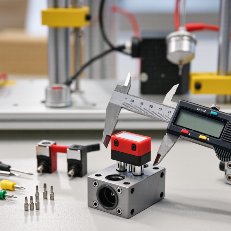
How to Choose the Right Micro Switch for Your Application?

Define Load Requirements: Compare 0.1–16 A Ratings Under IEC 61058-1

How to Choose the Right Micro Switch for Your Application?

Define the load before choosing a micro switch. Ratings from 0.1 to 16 A are not interchangeable. Under IEC 61058-1, performance depends on voltage, current, power factor, temperature, and switching endurance. A 16 A rating usually applies to a specified resistive load. Motors, solenoids, and capacitive circuits can create higher inrush current. That brief surge may weld contacts or accelerate erosion. A 0.1 A signal circuit has a different problem. Low current may not clean the contact surface reliably. The printed rating alone can mislead.

Compare the actual load with the test conditions in the datasheet. Check AC or DC operation, contact configuration, switching speed, and required cycles. IEC 61058-1 testing evaluates safety and endurance under defined conditions, not every field situation. Safety certification reports and laboratory test records deserve more weight than marketing tables. For a heater drawing 10 A at 250 V AC, a 16 A resistive rating may fit. For a compressor, it may not. Extra margin is sensible, but excessive oversizing can weaken low-level signal reliability. This part needs careful reflection.

Tips: Measure startup current with a suitable meter, especially for motors and transformers. Keep terminals away from heat sources. Test the switch inside the finished enclosure, not only on a clean bench. Record contact temperature after repeated operation. If the load changes during operation, recalculate the selection. A small error here becomes expensive later.

How to Choose the Right Micro Switch for Your Application?

Compare rated-current options from 0.1–16 A under IEC 61058-1. The equivalent power values below are calculated for a 250 V AC resistive load using P = V × I; actual suitability depends on the switch marking, load type, inrush current, voltage, and operating environment.

Selection guidance: Choose a rated current above the application’s steady-state current and verify the rating for inductive, capacitive, motor, or incandescent loads, which may produce higher inrush or switching stress than a resistive load.

Match Actuation Force and Travel: Evaluate Typical 0.5–5 N Operating Ranges

Choosing a micro switch starts with the force a user or mechanism can safely provide. Typical operating forces range from 0.5 to 5 N, but the number alone is not enough. A 0.5 N switch may feel sensitive under a light cover. A 5 N model can resist vibration and accidental contact. Measure force at the actual contact point, not only at the actuator. Small linkages can change it dramatically. Consider travel too. Short travel suits compact mechanisms, while longer travel can tolerate alignment errors and provide clearer feedback.

During practical evaluations, use a force gauge and a simple travel fixture. Record operating force, release force, and total travel at room temperature. Then repeat the test after repeated actuation. A switch rated near 1 N may work well in a clean panel, yet feel unreliable when a stiff seal or return spring is added. Leave enough overtravel after the operating point, but avoid crushing the actuator. That balance is easy to miss. Check it slowly.

Select the force range from the complete assembly, including friction, spring rate, and expected user pressure. For hand-operated controls, 1–3 N often provides a practical starting point. For guarded or vibration-prone equipment, higher force may reduce false actuation. This is not a universal rule. Temperature, dust, mounting angle, and production tolerance can change the feel. Test under load. Prototype several samples, because one test piece can hide variation. Document measured values and acceptance limits before production, then reassess them during field trials. Real mechanisms rarely behave as neatly as drawings suggest.

Select Contact Materials for Voltage, Current, and Switching-Frequency Demands

How to Choose the Right Micro Switch for Your Application?

Contact material should match the real electrical load, not only the catalogue rating. Silver-based contacts offer low resistance and strong conductivity for power circuits. They suit motors, heaters, and control panels. However, arcing can gradually roughen their surfaces. Gold-plated contacts perform better with low-voltage signals because they resist oxidation. They are not automatically suitable for high current. A gold contact may fail quickly under repeated arcing.

Switching frequency changes the decision. IEC 61058-1:2016 defines endurance testing through operating cycles, with common test levels reaching 10,000, 50,000, or 100,000 operations, depending on product category and load. IEC 60512-2-1 also measures contact resistance under controlled low-voltage conditions. These figures provide useful comparisons, but they do not copy every field condition. A dusty actuator, inductive motor, or vibrating enclosure can reduce actual life.

Measure the inrush current, not just the steady current. For a small motor, the startup demand can be several times higher than its running value. Silver alloy or arc-resistant contact systems may be safer for that duty. For clean sensor signals, gold-plated contacts usually deserve closer attention. I would not trust the rating alone. Check load type, voltage, frequency, temperature, and wiring length together. One detail is easy to miss: switching at 30 operations per minute creates over 15 million operations yearly. That calculation can expose an unsuitable contact material before testing begins.

Choose Environmental Protection Using IEC 60529 IP54, IP65, and IP67 Ratings

How to Choose the Right Micro Switch for Your Application?

Environmental protection can determine whether a micro switch survives or fails in service. IEC 60529 ratings describe enclosure protection, not unlimited operating conditions. An IP54 micro switch resists harmful dust deposits and water splashes from any direction. It may suit indoor panels, control cabinets, and light machinery. IP65 provides dust-tight protection and resistance to water jets. It fits exposed equipment that faces regular cleaning or outdoor moisture. IP67 adds temporary immersion protection, usually up to one metre for 30 minutes. This rating is more suitable for equipment near washdown areas or possible flooding.

Tips: Match the rating to the real exposure, not the ideal environment. Check dust type, water pressure, immersion time, temperature, and cleaning chemicals. Inspect the cable gland, actuator seal, mounting surface, and connector too. One weak entry point can reduce the whole assembly’s protection. The switch body alone may carry a rating that the finished product cannot maintain.

In practical testing, operate the switch while considering vibration, cycling frequency, and actuator alignment. A sealed IP67 unit can still wear quickly if the actuator receives side loads. I have seen designs focus on water protection while ignoring condensation inside a cold enclosure. That mistake is easy to miss. Confirm the manufacturer’s test conditions and installation instructions before approval. If the application only needs splash resistance, choosing IP67 may add cost without meaningful benefit. If immersion is possible, IP54 is clearly inadequate. Field conditions are rarely perfect. Recheck the decision after prototype testing.

How to Choose the Right Micro Switch for Your Application? - Choose Environmental Protection Using IEC 60529 IP54, IP65, and IP67 Ratings

Evaluation Dimension IP54 IP65 IP67 Selection Guidance
Meaning of the first digit 5: Dust-protected; limited dust ingress is permitted, but it must not interfere with satisfactory operation or safety. 6: Dust-tight; no dust ingress is permitted. 6: Dust-tight; no dust ingress is permitted. Choose IP6X where fine dust, powder, or frequent cleaning could affect the switch mechanism.
Meaning of the second digit 4: Protected against water splashed from any direction. 5: Protected against water jets from any direction. 7: Protected against temporary immersion in water under specified test conditions. Match the rating to the actual water exposure, not simply to the expected weather condition.
Typical IEC 60529 water test Water is splashed against the enclosure from all practicable directions. Water is projected as jets against the enclosure from all practicable directions. Temporary immersion; for enclosures up to 850 mm high, the lowest point is 1,000 mm below the water surface, generally for 30 minutes. Verify the exact product test conditions and mounting orientation before approving a design.
Suitable operating environment Indoor equipment, protected outdoor locations, light spray, condensation, and occasional splashing. Outdoor equipment, washdown areas with moderate water jets, dusty machinery, and industrial control panels. Equipment exposed to temporary flooding, accidental submersion, heavy rain, or installation near water. Use the lowest rating that reliably covers the real environment, while allowing a reasonable safety margin.
Protection against dust and particles Good protection against harmful dust deposits, but not fully dust-tight. Fully dust-tight when the complete rated enclosure is correctly assembled. Fully dust-tight when the complete rated enclosure is correctly assembled. For abrasive dust or conductive particles, consider IP65 or IP67 and confirm material compatibility.
Resistance to water exposure Suitable for splashes, but not intended for directed jets or immersion. Suitable for directed water jets, but not automatically rated for immersion. Suitable for temporary immersion, but not automatically rated for continuous immersion or high-pressure jets. IP67 does not automatically replace IP65 for applications requiring water-jet protection; check whether both tests are specified.
Examples of application conditions Covered machinery, indoor appliances, electrical cabinets, and devices exposed to occasional splashes. Factory automation, outdoor controls, agricultural equipment, and equipment cleaned with low-to-moderate pressure water jets. Low-position equipment, drainage areas, portable equipment, and devices that may be temporarily submerged. Base the choice on the worst credible exposure during operation, cleaning, transport, and maintenance.
Micro switch construction items to verify Seal, actuator opening, housing joints, terminals, and cable entry should prevent harmful water and dust ingress. Check sealing around the actuator, cover, terminals, mounting surface, and cable or connector entry. Confirm seals, cable glands, connector interfaces, mounting hardware, and pressure equalization details are suitable for immersion. The rating applies to the tested configuration; modifications, damaged seals, or an incorrect connector can reduce protection.
Recommended choice Choose when splash resistance and moderate dust protection are sufficient. Choose for dust-tight protection and regular water-jet exposure. Choose when temporary immersion is a credible risk and the complete assembly is tested accordingly. Do not select a higher IP code solely by appearance; confirm electrical ratings, operating force, travel, life, temperature range, and certification separately.

Note: An IP code describes protection against solid foreign objects and water for a specific tested enclosure or assembly according to IEC 60529. It does not by itself define corrosion resistance, chemical resistance, UV resistance, pressure-wash suitability, or long-term waterproof performance.

Verify Mechanical and Electrical Life Through 100,000+ Cycle Testing

Choosing the right micro switch starts with the real operating conditions, not only the catalog rating. A switch used in a control panel may face dust, vibration, repeated impact, or narrow temperature changes. These details affect contact stability and actuator wear.

Verify both mechanical and electrical life through 100,000+ cycle testing. Mechanical testing checks whether the actuator, spring, and housing still move correctly without electrical load. Electrical testing applies the intended voltage and current while monitoring contact resistance, bounce, and switching consistency. Use the actual load whenever possible. A resistive lamp load may produce different stress than a motor or relay coil.

Test evidence should include cycle speed, force, load type, temperature, and failure criteria. Without these details, “100,000 cycles” can sound stronger than it is. It is only meaningful when the test reflects your application. Review samples from different production batches, because one excellent sample cannot prove long-term reliability. Small variations matter. A switch may pass the cycle count but show rising resistance near the end. That result deserves investigation, not an easy approval. Also check the recovery period and inspect worn contact surfaces after testing. Careful verification reduces unexpected maintenance and helps match the micro switch to its actual job.

Amet mattis vulputate enim nulla aliquet. Id porta nibh venenatis cras sed felis dictumst vestibulum rhoncus est.
This error message is only visible to WordPress admins

Error: No feed found.

Please go to the Instagram Feed settings page to create a feed.

Quick links